


A digital solution to assemble large machine tools accurately
Tekniker and Zayer develop innovative measuring software
The technology centre and Zayer have worked together to design and develop a software solution within the framework of the Precision 4.0 project to ensure a higher degree of accuracy when laser technology is used to assemble machine tools.
Correct machine tool assembly is a must for a machine tool to meet precision requirements throughout its entire service life as this minimises maintenance interventions, delivers high-quality production and reduces maintenance costs.
It is in this context that Tekniker, a member of the Basque Research and Technology Alliance (BRTA), is currently working to improve the accuracy of large machine tools by means of an “error-free” assembly process equipped with digital measuring and monitoring tools.
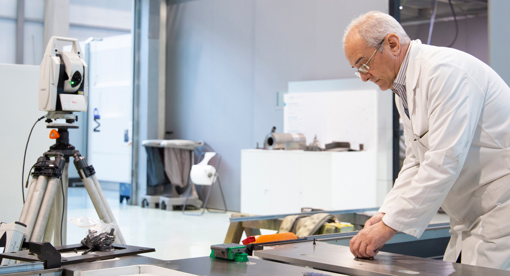
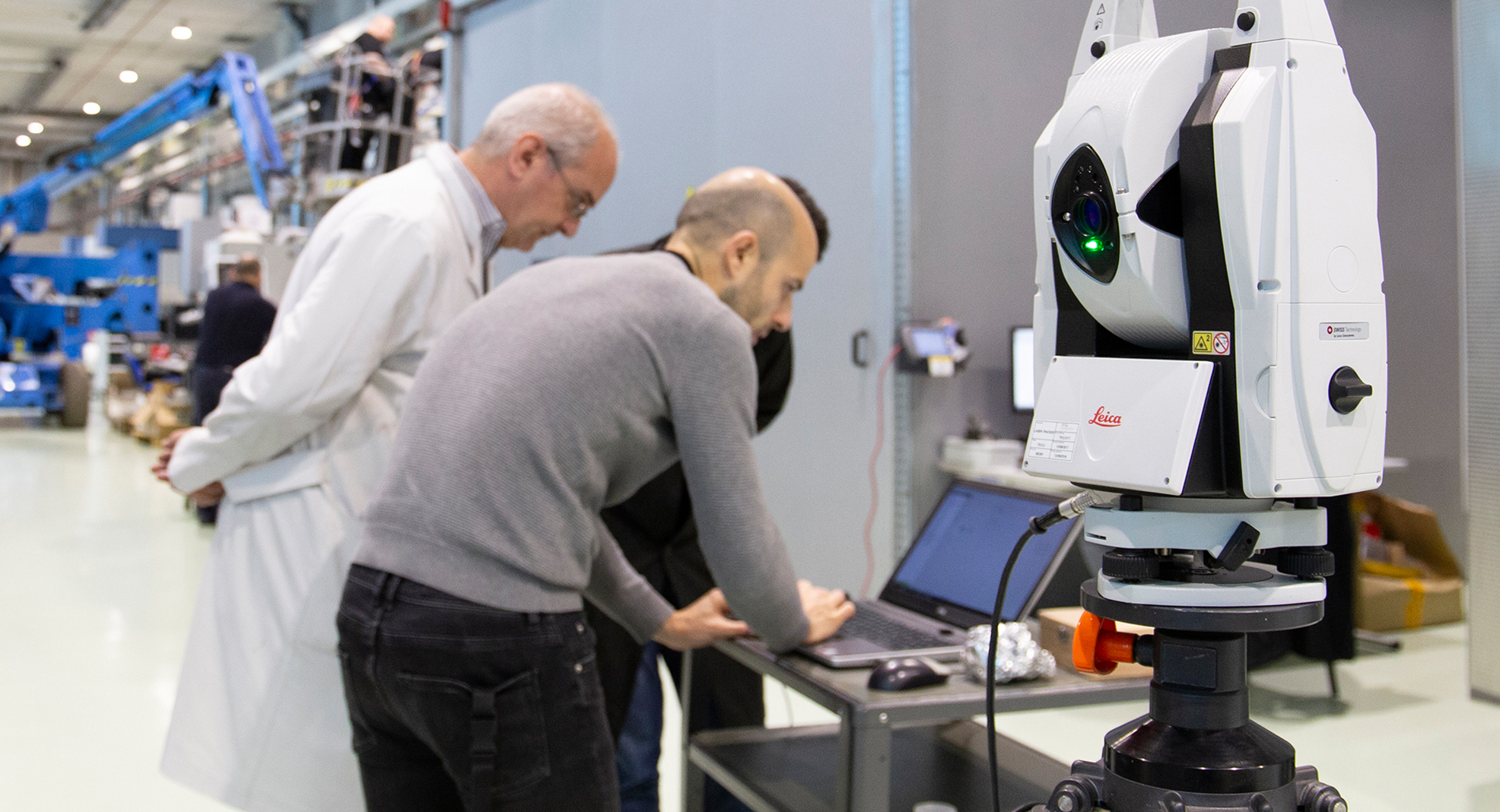
One of the best examples of this know-how can be found in the so-called Precision 4.0 project where the Basque technology centre has collaborated with Zayer, a company specialised in machine tools. The end result of this partnership is an innovative software that assists accurate machine tool assemblage processes by using Laser tracker technology.
Thanks to this innovative measuring system it is now possible to improve the accuracy of machine tool assemblage, minimise the amount of time required and ensure process traceability as with this software it is possible to digitise the entire process and collect key information. This measuring system covers a number of steps when assisting an assemblage process.
Firstly, a number of relevant geometric components of the assembly process are defined, such as, among others, positioning, levelling, straightness, bed height and perpendicularity between the elements used as a reference to quantify position and relative orientation between components.
The next step consists in defining the elements to be measured to set up a local system of coordinates and estimate the position and orientation of all other elements to be aligned.
Several probing tools are used to acquire measuring points. This allows information to be obtained on highly interesting positions on the guide, for instance, or on the skid itself.
Once the coordinate system has been set up, the next step consists in measuring those components to be placed in the space to ensure proper machine tool assemblage.
Next, the skids are mounted and checked to make sure all geometry requirements are met when in motion. Once mounted, the skids allow the columns to slide along the beds and checks must be performed to ensure that bed perpendicularity, positioning and parallelism meet measuring requirements. Parallelism relative to the columns and the beds is verified once the crossbeam is installed.
Finally, the entire subassembly (ram and head) is mounted and key geometry requirements are checked again.
The process measures and records assemblage information. It also displays the coordinates of points of interest in real time on-screen which allows the person in charge of the assembly process to correct the position and orientation of the body inside the space.
In this manner, it is not only possible to assist the assembly process of a large machine tool by improving accuracy and reducing costs, but also to digitise the assembly process itself step by step.
All of the information is recorded digitally and is readily available to perform final machine tool adjustments. It is later included in the project data base and made available to the customer.
This solution allows traditional measuring tools to be replaced by only one measuring instrument. The sole exception, however, is the final levelling process for components (better than 10 μm) for which level gauges still have to be used.
Measurements made in the different steps of the assembly process are traced to the International System of Units (SI) by means of the calibration certificate of the Laser Tracker measurement system that has been used.